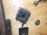
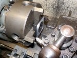
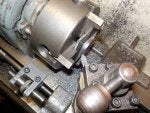
Decided to give myself an early Christmas present so I ordered an OXA series quick change tool post for the Craftsman (Atlas) 6" metal lathe that I think will be a benefit by adding some rigidity in the tool post area when turning and boring. Years ago I made a 4 way tool post and a boring set up that has worked well over the years but for the last five years or so I have been thinking that a quick change style would be nice as they are a sturdier set up and also offer the ease of quickly changing tool bits by switching holders and also being able to remove the tool post, sharpening a bit and returning it back to its position quickly. Thought I would do a post on it since other member may be interested. These are pictures of the boring and turning set up I have been using - they are ok but they require shimming if you need to adjust the height of the tool bit in relation to the center line of the lathe spindle which I find can be tedious as my eyes get older.
![]()
![]()
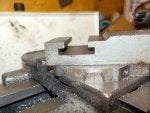
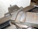
The OXA series tool post is the smallest that is offered and designed for lathes with a 6" to 9" swing - the Atlas has a 6" and the compound slide is made with a T slot to mount the any tool post that holds a tool bit. A lot of small older metal lathes were designed this way - most of the newer lathes have a hole for the tool post stud to thread into in the compound slide.
![]()
![]()
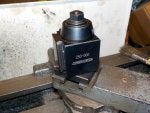
I set the new tool post on top of the compound slide and it looks like it should fit ok but the first order of business is to create a new T nut to fit into the T slot on the compound slide. The tool post comes with a piece of machinable metal that the stud that holds the new tool post threads into but because lathes vary in designs the piece is left lots large and thick and it is up to the purchaser to finish the metal piece to create a T nut specific to their lathe dimensions. This can be a challenge if you do not own a mill (or milling attachment) - I do have a milling attachment for my lathe but a lot of people don't so I decided to try machining the piece of metal using the lathe and some other tools that most people might have access to. This may not be the prettiest T nut and a true machinist may roll their eyes in disgust at my method - for this I apologize for in advance. Here is a picture of the new tool post sitting on the compound slide - you can see the bottom piece of metal at the base of the tool post that will be formed into a T nut (I hope).
![]()
The first thing I did was mount the metal piece in the 4 jaw chuck so I could start to turn the step so that the outer part of the step will slide into the T slot. Initially I turned only the outer edge as I needed the tool bit to be on a bit of an angle so I could clear the jaws of the chuck. Once I had the outer area roughed out I switched to turning the inner part of the step leaving a 1" diameter section untouched where the stud threads into it. I also added a small scrap piece of 1/8" x 1-1/2" thick flat steel to space the piece I was turning out so the tool bit did not hit the chuck jaws.
![]()
![]()
![]()
Once I had the step turned down to where it was the correct thickness for my T slot I cleaned the turned up area with a flat file.
![]()

The OXA series tool post is the smallest that is offered and designed for lathes with a 6" to 9" swing - the Atlas has a 6" and the compound slide is made with a T slot to mount the any tool post that holds a tool bit. A lot of small older metal lathes were designed this way - most of the newer lathes have a hole for the tool post stud to thread into in the compound slide.
I set the new tool post on top of the compound slide and it looks like it should fit ok but the first order of business is to create a new T nut to fit into the T slot on the compound slide. The tool post comes with a piece of machinable metal that the stud that holds the new tool post threads into but because lathes vary in designs the piece is left lots large and thick and it is up to the purchaser to finish the metal piece to create a T nut specific to their lathe dimensions. This can be a challenge if you do not own a mill (or milling attachment) - I do have a milling attachment for my lathe but a lot of people don't so I decided to try machining the piece of metal using the lathe and some other tools that most people might have access to. This may not be the prettiest T nut and a true machinist may roll their eyes in disgust at my method - for this I apologize for in advance. Here is a picture of the new tool post sitting on the compound slide - you can see the bottom piece of metal at the base of the tool post that will be formed into a T nut (I hope).
The first thing I did was mount the metal piece in the 4 jaw chuck so I could start to turn the step so that the outer part of the step will slide into the T slot. Initially I turned only the outer edge as I needed the tool bit to be on a bit of an angle so I could clear the jaws of the chuck. Once I had the outer area roughed out I switched to turning the inner part of the step leaving a 1" diameter section untouched where the stud threads into it. I also added a small scrap piece of 1/8" x 1-1/2" thick flat steel to space the piece I was turning out so the tool bit did not hit the chuck jaws.

Once I had the step turned down to where it was the correct thickness for my T slot I cleaned the turned up area with a flat file.