Garden Tractor Forums banner

Honda GX390 Charging System Upgrade From 3 Amp To 10 Amp Output

36K views 30 replies 4 participants last post by  29 Chev  
#1 ·
Back about 2007 I purchased a Bolens 1050 tractor that had a small Honda manual start engine installed on it. The original Wisconsin engine had a broken camshaft along with other problems and was included in the deal as a basket case. The Honda engine installation was not very well done and since it left the 1050 underpowered at around 6 HP - the original Wisconsin was rated at about 10.5 HP. I priced out repairing the Wisconsin and decided that I could purchase a brand new Honda GX390 engine with electric start for less money which I did. I relocated the air filter and created a new exhaust pipe which allowed me to install the engine without cutting the hood and things moved ahead nicely and after about a month I had the engine installed and running. It gets used regularly and I have found the Honda GX390 to be a good reliable engine over the years. One thing that I did not give much thought to initially when I purchased the engine was the output rating of the charging system since it had electric start. What I found out after I got the engine mounted was that the model I had purchased only had a 3 amp charge coil and did not utilize a true voltage regulator / rectifier that one would normally find on higher output charge systems. Instead the 3 amp coil output was fed into a diode and designed to provide a D.C. trickle charge to maintain a battery for starting. As a result the electrical load required to run two sealed beam headlamps and a taillamp left the ammeter showing a discharge whenever the lights were switched on. I had priced purchasing a 10 amp or 18 amp charge coil set up along with a Honda voltage regulator and the price was more than I wished to spend so I opted for an alternative. I came up with a plan and initially made a 4 pole stator (patterned after the 18 amp stator) out of some metal plates and wound the poles with 16 gauge magnet wire along with a full wave rectifier / regulator that was rated for 15 amps and my home brew system provided approximately 8 amps of current which was adequate to maintain the battery with the lights on. This worked well for about a year and then the stator developed a short in one of the windings - probably caused by excessive eddy currents which create heat since the metal plates I used were thicker than a normal stator laminated set up.
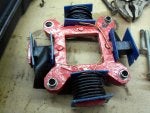
Attached are pictures of the original 3 amp charge coil and a picture I took of the first stator I made. Back then I was not much for taking pictures and documenting things so I am going off memory for the most part.
 
Discussion starter · #2 ·
When the first stator stopped working I made a second stator out of sheet metal plates and installed it (sorry no pictures) and it worked well for several years but for the last six years or so it has developed a desire to be intermittent at higher RPM's and as a result it only charges at lower engine speeds. It keeps the battery charged but I tend not to run the lights very much when blowing snow with the tractor so that the battery dies not get excessively drained. I have been keeping my eyes open for another Honda GX390 with a 10 amp charging system but have not had any luck so this winter I was looking on the web to see what the 10 amp charge coil set up was priced at and I found one in Japan that I have taken a change and ordered. It was shown on Amazon in the U.S. and I was able to purchase it for about $110.00 Canadian when the exchange rate was figured in. The coil set up arrived today and is in a Honda package and appears to be a genuine Honda part. The package was shipped from Japan and of course had to be brokered through Canadian Customs which the shipping company did and I had to pay GST on the value so the total bill for the coils is about $150.00 Canadian. I had priced them in Canada online and from a dealer and about the best price I had found was around $170.00 plus tax and shipping so I am still happy with the price of the charge coil set up I received.

I have learned a lot about the Honda GX390 charging coil setups since then and I will note that when I did my second repower with a Honda GX390 (about 2015) I had learned my lesson and I ordered an engine that came with an 18 amp charging system and the rectifier / regulator was included. The price between that setup and one with the 3 amp system was only about $100.00 more so it was well worth getting the upgraded charging system when I purchased the new engine.

I am hoping this spring when the weather warms up that I can get the higher amperage charge coil set up installed and be able to use my existing regulator to create a reliable charge system capable of outputting enough current to run the lights and maintain the battery. I decided to start a post on the upgrade as it may help others who have a Honda GX390 with a 3 amp system and the information may also be helpful to anyone with a clone of this engine as I hope to post sizes of the coils and details of the Honda flywheel. The sizes may help someone decide if the Honda system might be adapted to a clone. As near as I have been able to determine looking at the parts list the flywheel that came with my QAE6 sub model 3 amp electric start set up is the same part number as the flywheel that was used with the 10 amp setup such as might be found on a QNE6 sub model. It is my hope to update this thread from time to time as I make progress.
For now here is a few pictures of the 10 amp charge coil set up that I got today- there are two coils that are wired in parallel and the two wires from each coil are joined inside the harness so that the connector only has two wires which should produce about 30 volts AC which is similar to what a normal multipole stator would produce.
 
Discussion starter · #3 ·
I took some measurements today which may be helpful to compare the Honda 10 amp charge coil thickness and mounting hole center to center distance with a clone engine.
Image
 
Discussion starter · #4 ·
Thought I would post the Honda wiring diagrams that show the various options that were offered for the charging systems. The engines that were designed to be strictly manual start were less expensive but the flywheels did not have any internal magnets or ring gear and would have to be changed to upgrade for use with an electrical starter and charging system. The magnet that triggers the ignition coil is located on the outside of the flywheel. The charging systems were offered as a 1/3 amp, 10 amp and 18 (20) amp option. The 1/3 amp had one of the wires of the winding for the charge coil connected to the coil core which served as a ground connection. The other wire fed AC current to a diode which provided half wave rectification as the negative half of the AC wave would not pass through the diode. It might be possible to unhook the coil wire from the core and add a second wire to provide a floating AC current that could be connected to a full wave rectifier / regulator but I ma not sure how much this might increase the current output if any since the wire winding appears to be about 18 or 20 gauge on the 3 amp coil. I have also attached a technical manual that contains a lot of good information on the sizes and dimension of a Honda GX390 engine as well as other information such as using the engine with a non stock exhaust system. The wiring diagrams show the newer style ignition coil with four terminals - two of these terminals must be connected together to obtain an ignition spark. The older style coil (which my 2007 engine has) will provide spark unless the one terminal is connected to ground. I believe this was done as a safety upgrade so that the engine would not start if the ignition coil was not connected to the wiring harness.
 

Attachments

Discussion starter · #5 ·
Here is an enlarged view of the 10 amp charging system wiring diagram. It shows the two charge coils are connected in parallel to form a floating AC current source that is connected to the six terminal Honda rectifier / regulator. The flywheel magnet illustration shows only two magnets compared with four shown in the 18 amp system but if memory serves me correctly the flywheel on my engine has four internal magnets - not sure if this will create any issues or not - could just be a typo . The six terminal connection set up that Honda used on their regulator / rectifier may be confusing at first since most permanent magnetic charging systems and full wave rectifier/regulator setups usually only use three terminals and the rectifier/regulator case is connected to ground - two AC wires in and a positive wire to supply regulated DC to the battery. Two of the wires on the Honda voltage regulator - the positive regulated DC out and what I will call a sense wire to monitor battery voltage are connected together. There are two terminals that the AC from the charge coils is connected to. There is one terminal that connects to ground rather than relying on the case of the regulator to complete the ground circuit. The last terminal is not used - I believe this terminal is used for some applications that may have a charge light or it may be a test terminal. As I stated earlier it is my hope that the AC current supplied by the new charge coils can be connected to my existing full wave three terminal regulator and that they will play nice with each other. If not I may have to invest in a Honda regulator/rectifier designed to work in the 10 amp circuit - time will tell. I have also included a diagnostic chart in pdf format that I found which shows how to test the various charging systems if they are not working properly.
Image
 

Attachments

Discussion starter · #6 ·
I finally found the original 3 amp charging coil that came installed on my engine - I had it well hidden and it was safe from anyone finding it easily - including me. Took a few pictures of it beside one of the charge coils that make up the 10 amp stator setup. Was able to measure the diameter of the wire on the 3 amp coil where it is soldered to the stator frame and came up with an O.D. of .032" which equates to 20 gauge solid wire according to the solid wire size chart I found online. I cannot get a measurement of the wire diameter that is on the 10 amp coils without removing the tape (which I am not going to do for obvious reasons) but I am guessing that they are probably wound with 16 gauge wire to get a higher current output. Looking at the coil form and sizes where the tape is they appear to be physically about the same so the number of windings on the 10 amp coils will be less turns since the wire diameter is larger. The actual coil form and core appears to be identical with the same number of segments making them the same width so I should be able to reuse the bolts that came with the original coil. I cannot remember whether the second new stator I made is the same thickness as the original coil or not - will have to wait until I get the flywheel off of the engine. It would be interesting to know how the two 10 amp coils are wound as I assume one coil would be a mirror image of the other so that the two AC pulses generated add rather than subtract from each other. Been looking online but so far have not found any information on the actual windings.

Come on spring weather.

 
Discussion starter · #7 ·
With the temperatures getting above freezing I am starting to do some prep work for installing the new charge coils. To do this will require removing the flywheel and the Honda manual I found online shows using 3 socket head bolts with collars and a 3 hole style puller. If memory serves me correctly the bolts I used last time were hex headed 6 mm x 1.0 x 45mm (ISO Course) and I found three of them yesterday in my stash of metric hardware.

The last time I pulled the flywheel I used a regular harmonic balancer / steering wheel puller that was designed to be used with 3/8" diameter bolts in the slots and I had to use some nuts, washers and hold my face correctly to get everything set in place so the smaller metric bolts heads sat flat against things and pulled evenly on the flywheel. Today I decided to turn 3 collars to make things a bit easier when pulling on the flywheel using the puller. They are made out of 3/4" round steel stock .420" in length with a 1/4" hole drilled in the center and the outer diameter of the smaller portion is turned down to 3/8" so it will fit nicely in the puller slot. The larger button area I left at .750" and is .200" thick and will act as a nice thick washer for the bolt head to sit flat against and the collars should sit centered and flat in the puller slots.
 
Discussion starter · #8 ·
Yesterday it was a wet icky day so the outside chores got cancelled and I decided to start removing components on my Honda GX390 that hopefully will allow me to replace my home made stator to the factory versions. First the hood was opened up and supported with a couple of plastic totes so I could have better access to the front of the engine


Removed the fuel line from the plastic clip that it usually sits in on the fan shroud and removed the three bolts that hold the recoil to the fan shroud using a 10 mm socket.


Next I removed the 5 bolts that hold the fan shroud to the engine - there are two on the top and three on the bottom side. These also required a 10 mm socket.


This allows access to the ignition coil and the flywheel area of the engine.


The flywheel nut is recessed inside the recoil drive hub so it requires either a deep socket or a socket and extension to get on it.

 
Discussion starter · #9 · (Edited)
The flywheel nut is metric but I have a deep 15/16" six point socket that is a reasonably snug fit on it so I used a 1/2" drive swing bar to loosen the flywheel. I used a pry bar to catch a ring gear tooth to keep the flywheel from turning.


Once the flywheel nut was removed I could then remove the plastic fan and the drive hub which holds the fan on. The fan has three protrusions molded onto the inner face that fit into three holes in the flywheel and there is one protrusion on the hub side of the fan that fits into a hole in the metal hub. This allows the fan to aligned as it is sandwiched in between the hub and the flywheel.


With the fan and hub out of the road I then threaded the flywheel nut back on flush in anticipation of using a harmonic balancer puller and the three bolts I though I had used years ago that I made collars for.


Unfortunately I found out that the three bolts I thought I had used were too short to work with the puller so I put my thinking cap on and tried to remember how I had removed the flywheel years ago. After thinking for about 15 minutes and having a look in the drawers of the tool box that I stash special bolts and trinkets in I finally had an aha moment and found the bolts I had used before. What I had done was to take three 5/16" diameter bolts about 2-1/2" long and turn down the threaded end using the metal lathe so that I could cut 6 x 1.0 mm threads using a die. The three puller holes in the flywheel are blind so I had made them about 1/2" long and the 5/16" diameter bolt heads were large enough that I did not need washers to keep them from pulling through the slots in the puller body. I found out that I should have used longer bolts back then as I had to remove the pilot end of the puller screw to have enough threads of the puller engaged with the screw but it did the trick again and the flywheel came loose.


I used a flat screwdriver in the teeth to hold the flywheel while I tightened the puller screw. I removed the puller and the flywheel nut but I found out I still had to loosen and remove the two bolts that hold on the ignition coil before I could remove the flywheel as I somehow had it in the back of my mind that I didn't have to remove it years ago. I think that with only the one three amp charge coil in place there is enough wiggle room that the flywheel can be slid out and tilted to remove it but with a 10 amp charge coil set up or my homemade stator with four poles the flywheel must come straight off so I used a 10 mm socket to remove the two bolts and let the coil rest out of the way and the flywheel was then removed.
 
Discussion starter · #10 ·
Here is a picture of the inside of my flywheel and I noticed there was a bit of rust on the 4 magnet shoes so I decided that it might be prudent to clean things up a bit and give the inside a squirt of paint to slow the rust down a bit.


Here are pictures of my homemade four pole stator which I had patterned after images of the 18 amp stator version. There is evidence of heat from the looks of the tape being melted so I am guessing that as things get warm and the rpms increase that one of the coils is grounding out somewhere. The heat may be the result of eddy currents as while my stator is laminated pieces of metal to cut down on them the sheet metal material that I used is probably not the same material as what the OEM stators are made from. As you can see in the last picture the two bolts at the top are the original ones that held the 3 amp coil and the two bolts at the bottom are aftermarket with flat washers but since they have stood the test of time I will try and reuse them.

 
Discussion starter · #11 ·
Removed the four bolts and the homemade stator got removed along with the wire guide that protects the wiring from the stator to where it exits at the side of the engine.


The new 10 amp coils got installed in its place and the wires from the two coils were routed on the inside of the mounting posts and the wire guide was installed again to secure them from harms way.


The upper coil is mounted in the same position as the 3 amp coil is installed from the factory.
 
Discussion starter · #12 ·
The flywheel magnets got cleaned up with a light sanding and painted with some grey rust paint. The four magnet shoes on the inside along with the ignition coil magnet on the outside of the flywheel are all secured in place with a machine screw. Took pictures of the two numbers that are visible on the inside of the flywheel.


The flywheel then got slid back on to the crankshaft making sure that the key was aligned and stayed in place.


There are 3 holes in the flywheel to accept three protrusions on the flywheel side of the plastic fan - they are offset in location so that the fan can only be mounted in one spot in relation to the flywheel.
 
Discussion starter · #13 ·
Once the fan is set in position the dimple on the outside can be seen that fits in the hole of the hub to align it - again it is designed to be installed in one spot in relation to the flywheel.


The flywheel nut was then installed and torqued to 83 ft. lbs. making sure that the fan and hub stayed in position - I used the prybar on the ring gear tooth to keep the flywheel from turning as I tightened the nut. It should be noted that there is a series one and series two in the GX390 family and the first series have a torque spec of 83 ft. lbs. for the flywheel nut. The nut on the series two engines is the same thread size from what I have been able to find out but the torque spec for that nut is much higher at 125 ft. lbs. I then rotated the flywheel a few revolutions and did not hear any scraping sounds or notice any binding so things looked good as far as the new coils clearing the magnets.

Next the ignition coil bolts and coil got installed and the air gap set - the spec shown in the service manual is .016" + or - .008". I found a piece of cardboard about the same thickness as a business car and measured the thickness of it with a micrometer and found it was .018" thick so it got cut into a strip and served as my feeler gauge. The manual shows to place the flywheel so that the ignition coil magnet is not at the coil position and to use the outside of the flywheel to set the feeler gauge on and then push the coil arms down so it is snug sitting on the feeler gauge and then tighten the mounting bolts so that is how I set the air gap. Afterwards I gently turned the flywheel which released the trapped carboard strip.


Next the shroud got installed and then the recoil.


Since my homemade wiring harness used bullet style connectors to connect the stator wires I simply cut a section of the wires from the homemade stator and attached two 1/4" male spade connectors to the cut ends and inserted them into the factory plug that the 10 amp coil wiring came with. Then I reinstalled the bullet connectors to the wiring harness and then reconnected the negative battery cable that I had removed when I started to take things apart. I was now ready for a test run to see if the new coils would work with my generic three terminal full wave rectifier regulator that I have been using since I repowered the tractor.

 
Discussion starter · #14 ·
Started the engine and the first thing I noticed was that the ammeter showed it was charging about 2 amps at a little above idle so that was a good sign. Shut the engine off and turned the lights on and found out that the left headlight decided it was done playing and needed replacing so I grabbed a spare 4411 seal beam I keep on hand and got it installed. Once that task was done I turned the headlights on for a couple of minutes to discharge the battery. For those who are purists the 4406 are the number listed as the factory lamps on a 1050 but I find the 4411 are usually a couple of dollars cheaper and work ok for my needs.


Then I started the engine and turned the lights on with the engine just above idle and noticed the ammeter was sitting at 0 - it showed about a 2 amp discharge at idle and if I revved the engine up to about 2000 rpm the needle showed about a 2 amp charge.


Then I shut the lights off and the ammeter was reading about 8 amps at higher rpms. Not quite the 10 amps that the coils are rated at but still should keep the battery charged with the lights on while blowing snow and I would say that the reading is about 1 amp higher than what my homemade stator would show with the lights off. The reading quickly dropped back as the battery got charged back up. Will try and do a video in the next day or two as time permits to show how the ammeter needle responds. So right at the moment I am quite happy with the results from the new coils - not quite 10 amps output according to the ammeter but it may be off a few amps and the other factor might be that I am not using the original Honda regulator that the coils were intended to be used with. This is a picture of the regulator that the charge coils are working with.
 
Discussion starter · #15 ·
Here is a link to the video that shows the ammeter response with the headlights on and off with the engine running at idle and revved up.

 
Discussion starter · #16 ·
Ran the 1050 tractor for a few hours yesterday while grading the lane and the charging system stayed working fine - checked a few times to see what the ammeter showed with the lights on and all looked good. Cut the grass today using my other 1050 which has the 18 amp charging system Honda and observed the ammeter on it with the lights on and it needs to be running at around 2000 rpms with the lights on before it stops showing a discharge on the ammeter. The new 10 amps charging coils with the generic regulator seem to behave similarly and show a charge at around 2000 rpm and higher so things appear to be working the way they should be.
 
Discussion starter · #18 ·
How did you make your air intake set up? What size tubing and elbows did you use and how did you make that part coming off the carburetor?

I am in the process of doing a 420cc Predator swap on my 1977 Bolens G10/1055 garden tractor.
Check out this thread as it should answer most of your questions - Bolens 1050 Repower With Honda GX390
The hose and elbows were 1-1/4" if memory serves me correctly and the thread should show you how I made the adaptor plates for the carb and the air cleaner housing.
 
Discussion starter · #20 ·
Do you think it would be feasible to run an alternator/generator on a setup like this? I recently picked up a 2nd hand GX390 for my 1050, will be starting that install in a couple weeks. I don't think I have the high output charging system, but I was thinking about a generator or alternator install before I came across this post. Do you think there's room? Is it smarter just to update the coils like you did?
If your tractor does not have the hydraulic lift option you might be able to mount a small car alternator near where the hydraulic lift went and drive it with the pulley belt groove that is between the drive belts and the PTO belts - would have to make sure there was enough room and that the alternator did not interfere with any lift linkages such as front mounted blade or snowcaster. Would probably want the alternator to turn in the same direction as it did on the car application and it would need a V belt groove pulley to be driven off the middle groove on the stock engine pulley. If you cannot mount it there then you would need to add a pulley somewhere else to drive the alternator (perhaps at the front?) and mount it there - you would probably have to adapt a pulley somehow to the flywheel as I am not sure how you would bolt it directly to the flywheel with the plastic fan which is held on with the crankshaft nut. If you have the model series and serial number of the GX390 (should be stamped on the left side of the block near the bottom) you should be able to look up the charging system parts and see what it has from the factory and also what flywheel it has - I assume it has electric start and has charging magnets on the flywheel. A 3 amp charging system would keep the battery charged but probably not provide enough power to run incandescent lights continuously but if you were only using the tractor during daylight hours or needed the lights only for short periods of time that probably would not be a factor. I use my tractor at night and before sunrise for snow removal duty in the winter time and the incandescent lights (2 headlamps and taillamp) require about 7 amps to power them. You might also consider changing to LED bulbs and as a result not require very much current to power the lights. Updating to the higher amperage charge coils made sense for me as I already had a rectifier / regulator installed for my homemade stator but if you have to purchase both the charge coils, a rectifier / regulator and possibly a different flywheel then an alternator or LED lighting may be a less expensive way to go depending on your needs and how good you are at making brackets and how economical a used alternator is for you. Another option to consider would be to just hook a battery charger up to the tractor when you were done using it to replenish the battery if you had been using the lights so it was ready to go the next time you needed it. On my tractor I like the fact that the charge coils are under the flywheel and don't require any additional brackets or pulleys or extra room for an alternator as I have a homemade hydraulic lift using a GM power steering pump to lift attachments that is mounted and driven where the hydraulic lift that Bolens offered would go.
 
Discussion starter · #22 ·
I don't have the hydraulic lift but would love one. The snowcaster and tiller are especially hard to lift with the manual handle!
There was also a spring assist kit that was offered by Bolens for the Tube Frames with the manual lift. You might be able to fabricate something similar to help lift the heavier attachments. Attached is a pdf of the instruction sheet.
 

Attachments

Discussion starter · #23 ·
Just an update - used the tractor with the updated charge coils all last winter with the generic rectifier regulator and the charging system stayed working but the last time I had to blow snow a couple of weeks ago I noticed that there was a brief period where the ammeter showed a discharge - same intermittent problem I had experienced originally. I am now thinking that the generic 15 amp regulator I have been using has an intermittent connection inside it that vibration (depending on engine speed) causes the regulator not to work occasionally.
I decided to order a generic 18 amp rectifier regulator that is supposed to replace the original Honda rectifier regulator part number 31620-ZG5-033. Since the other tractor I have repowered has a factory 18 amp charging system I thought it might be handy to have a spare regulator and I can use the original wiring harness to figure out the connections to the terminals. I am hoping that the 18 amp regulator will work with the 10 amp charge coils but this will be an experiment to see - time will tell. At the same time I ordered the regulator I also order a male / female connector kit that contains housings and terminals that have 2 to 9 wire connectors as it had 6 wire housings that I was hoping would mate to the original Honda housing on the regulator but they are a slightly different size. If the regulator works out I may still be able to remove the original terminals and install them into the one side of the housing and then configure the mating housing to plug into it but in the mean time I will just use individual terminals to connect the regulator to the tractor and see what happens.
Here is a picture of the housing and terminal kit which cost me about $25.00 - figured they will come in handy if I need to add or replace connectors to a wiring harness in the future.

Here is a few pictures of the regulator I purchased for about $40.00 - probably the quality is not as good as an OEM Honda one (I assume it is made in China) but the price is a lot easier on my tractor funds if this experiment does not work out.

Think I have the terminals identified that I need to connect to but will first have to make a mounting bracket to place the regulator on and spent a few minutes this morning determining where the best spot might be to mount the unit. Think I have a location figured out and hopefully the weather will be above freezing for a few days so I can get it mounted and connected to see if it works. The Honda 18 amp unit has 6 wires - as near as I can tell two are for AC input from the charge coils, one wire is ground, one wire goes to the battery positive, one wire is a sense or feedback wire so the regulator knows what the voltage level at the battery is (these two wires are connected together in the OE wiring harness on the 18 amp wiring harness on the other engine). The sixth wire I believe is to operate an indicator lamp to show if the unit is charging or not - for my purpose this wire will not be connected.